Cartpole Dynamics and Control
Introduction
As is the case for a lot of PhDs, my main work focuses on a small part of robotics. There are many areas of robotics that I would love to work on but do not. As part of my ongoing effort to learn more about these areas, I work on accessible problems that interest me. One area of robotics that fascinates me is that of rigid body dynamics and control. Regardless of how many times I see it, there is something magical about using mathematics to make correct predictions about the world. Newtonian mechanics - the science that powers most modern robots - is many hundreds of years old, but I can still feel the magic when the equations come to life.
One toy system that is commonly used to learn about dynamics and control theory is the cart-pole or inverted pendulum. Over the past few weeks, I’ve been working through simulating the dynamics of the system. I alse tried out some common control strategies to perform the task of balancing the pendulum with its center of mass above the joint. In this article I’ll go through the process from beginning to end. I think the cart pole system is very convenient as it is simple enough that its dynamics can be worked out by hand. Concomitantly, it is complex enough to warrant applying some advanced control strategies.
Modeling and Simulating the Cart-Pole System

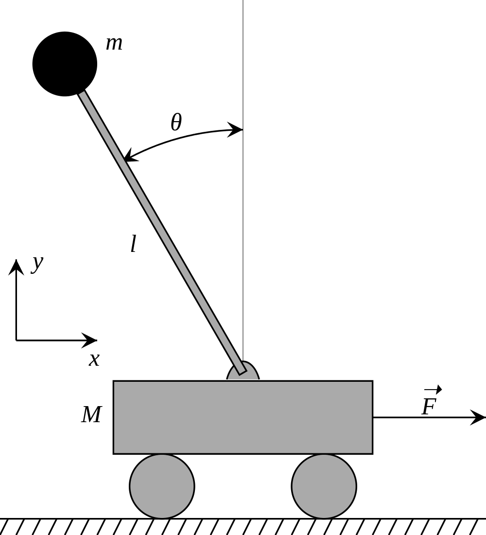
The diagram above (lifted from the Wikipedia article) shows what the system looks like. It is assumed that the cart is on a fixed linear rail (frictionless of course). This can be considered a prismatic joint in robotics terminology. The pendulum is mounted on the cart with a revolute joint that has a single rotational degree of freedom. There are a few ways to model the pendulum. Some model it as a uniform bar/cylinder and some as a concentrated mass at the end of a massless link. For the purposes of this article, I’ll be modeling it as a thin cylindrical rod.
Lagrangian Mechanics
Lagrangian mechanics is a fascinating and beautiful formulation of classical mechanics. Rather than the three laws of motion, Lagrangian mechanics is interested in a scalar quantity called the action which is a function of the state of the mechanical system. By applying a simple constraint known as the Principle of Least Action, you can get the equations of motion for any system in any coordinate system.
To apply Lagrangian Mechanics to the cart-pole system, I need to first write down the Lagrangian of the system which is defined as the difference between the potential and kinetic energies of the system as functions of the state.
Since the cart moves perpedicular to gravity, the potential energy $V$ only depends on the vertical position of the pendulum.
$$ V = -m_{p}gl\cos{\theta} $$
The Kinetic Energy of the system is a bit more involved. It’s the sum of the kinetic energies of the cart and the pole.
$$ \begin{align} T &= \frac{1}{2} m_c \dot{x}^2 + \frac{1}{2}m_p \left[ (\dot{x} + l\dot{\theta}\cos{\theta})^2 + (l\dot{\theta} \sin{\theta})^2\right] \\ &= \frac{1}{2} (m_c + m_p) \dot{x}^2 + \frac{1}{2} m_p l^2 \dot{\theta}^2 (\cos^2{\theta} + \sin^2{\theta}) + m_p l \dot{x}\dot{\theta}\cos{\theta} \\ &= \frac{1}{2} (m_c + m_p) \dot{x}^2 + \frac{1}{2} m_p l^2 \dot{\theta}^2 + m_p l \dot{x}\dot{\theta}\cos{\theta}\end{align} $$
The Lagrangian is then:
$$ \mathcal{L} = T - V $$
In Lagrangian mechanics, as the system evolves over time, a quantity called action is defined as the integral of the Lagrangian.
$$ S = \int_{t_1}^{t_2} \mathcal{L} dt$$
According to the Principle of Least Action, the dynamics of the system evolves so that this quantity - the action - is minimized. Once I have the action I can use the Euler-Lagrange equations to find the equations of motion of the system.
$$ \frac{d}{dt} \frac{\partial \mathcal{L}}{\partial \dot{q}_i} - \frac{\partial \mathcal{L}}{\partial q_i} = F_i$$
The $q_i$ represent the state variables of the system and $F_i$ generalized forces. By applying these equations once for each state variable I get the full equations of motion of the system. In the case of the cart pole system, the state variables are the position of the cart and the angle between the cart and the pendulum. The resulting two equations are:
$$ \begin{align} -m_p l \dot{\theta} \sin{\theta} + (m_c + m_p) \ddot{x} + m_p l \ddot{\theta} \cos{\theta} = F_1 \\ m_p g l \sin{\theta} + m_p l \ddot{x} \cos{\theta} + m_p l^2 \ddot{\theta} = F_2 \end{align} $$
The central equation of study in robot dynamics are the manipulator equations. These equations are a general way to express the dynamics of a multi-link rigid body. By inspecting the equations of motion derived above, they can be expressed in the manipulator equation form:
$$ H(q)\ddot{q} + C(q, \dot{q})\dot{q} + G(q) = F $$
Where
$$ H = \begin{bmatrix} m_c + m_p & m_p l \cos{\theta} \\ m_p l \cos{\theta} & m_p l^2 \end{bmatrix}$$ $$ C = \begin{bmatrix} 0 & -m_p l \dot{\theta} \sin{\theta} \\ 0 & 0 \end{bmatrix} $$ $$ G = \begin{bmatrix} 0 \\ m_p g l \sin{\theta} \end{bmatrix} $$ $$ q = \begin{bmatrix} x \\ \theta \end{bmatrix} $$
Simulating the Cart Pole System
There are a few ways to simulate a mechanical system once you have the equations of motion. Python is an excellent option. The scipy package has a good set of numerical integrators. You just have to feed in the initial conditions of the system and it’ll simulate the system for as long as you want (at least, until your RAM runs out). However, for this project, I chose to use MATLAB. Mathworks decided to make the student (and personal) version of MATLAB available for ridiculously cheap prices (compared to their organizational licenses). So about a year ago I bought their student license so I could learn to use it. Everything I do in this article can be done just as well using Python and scipy. However, I do admit that using MATLAB makes the work a little smoother.
For simulating the cart-pole I will be using the Simscape Multibody toolbox for Simulink.

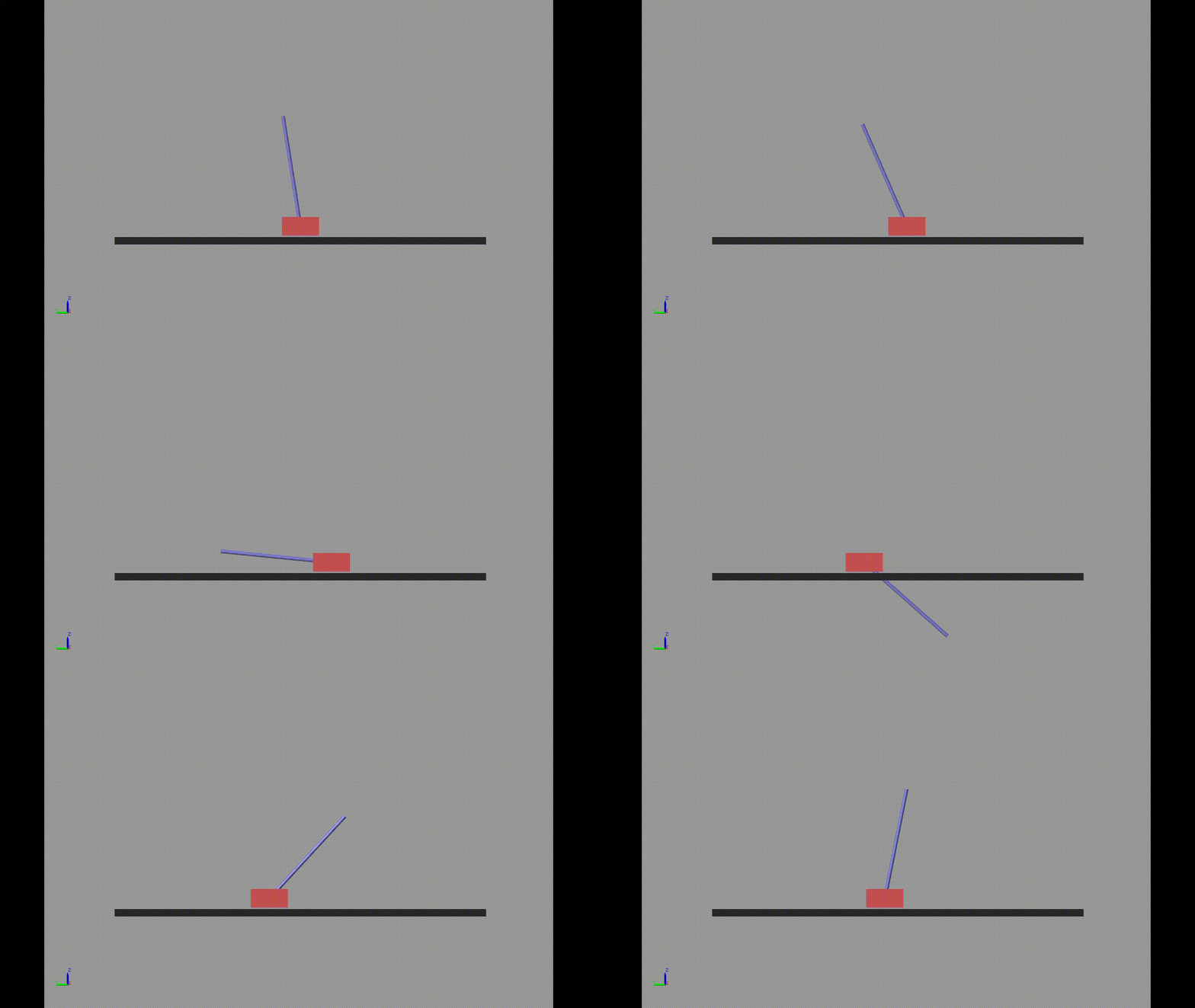
Without any kind of control system active, we can see the dynamics of the free system quite nicely.

Balancing Control
The balancing control task is that of having the pendulum balance with its center of mass above the cart by only moving the cart (there is no actuator on the revolute joint). The control input in this task is a force that is applied to the cart (through electric motors or rocket engines or some other means of actuation).
The cart pole system is a highly non-linear system. However, just like how the motion of the simple pendulum can be approximated by a linear system for small angles, the cart pole system can be linearized too. Sometimes in engineering, the approach of “fiddling with it till it works” really works! So the first thing I tried to do is to implement a simple PD controller. If the system is linear around the balancing point (which it is in this case) and long as the states aren’t too far off, this approach will work.
Hand-Tuned Control Gains
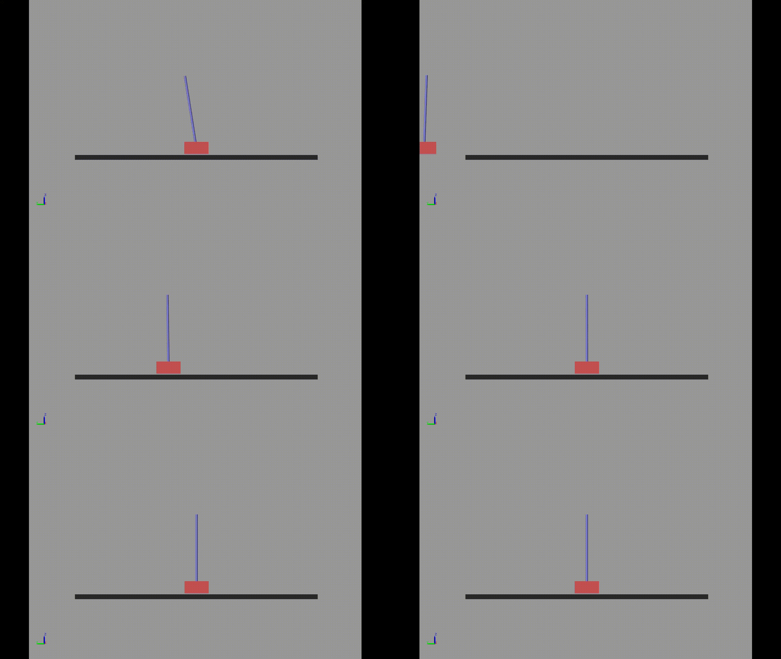
So the very first thing I tried are hand tuned control gains. I just assumed that I could achieve what I wanted by using the control signal $u = K\cdot s$ where $s$ is the state vector with the positions and velocities: $s = \begin{bmatrix} x & \dot{x} & \theta & \dot{\theta}\end{bmatrix}^T$. After a bit (a lot) of fiddling, I did manage to find a set of control gains that worked. Here’s what the controller looks like when it tries to balance the pendulum.

LQR
To avoid wasting all that time fiddling, control engineers invented a type of controller called a Linear Quadratic Regulator. LQR controllers formalize the process of fiddling by defining a cost function on the states and control inputs. The optimal control gain vector $K$ is the vector that minimizes this cost function. LQR is fundamental enough in control theory that standard functions exist to calculate the control gains if you have the linearized system. Such functions exist in both MATLAB and scipy or specialized control libraries.
To do LQR, we first need to linearize the system around an “operating point”. This process can be little (but not too much) involved if you try to do it by hand so I applied liberal amounts Mathematica to help me out (you can do the same using SymPy in Python). I first expressed the equations of motion in the form $\dot{s} = f(s, u)$. This can be done by rearranging the manipulator equations. Once you have the dynamics in this form, the linearized equations of motion can be expressed as:
$$ \dot{x} = A(s - s^*) + B(u - u^{ *}) $$
Where
$$ A = \frac{\partial f}{\partial s}\Bigr\rvert _{s=s^{*}} $$ $$ B = \frac{\partial f}{\partial u}\Bigr\rvert _{u=u^{ *}} $$
For the cart pole system, the matrices come out as:
$$ A = \begin{bmatrix} 0 & 0 & 1 & 0 \\ 0 & 0 & 0 & 1 \\ 0 & \frac{m_p g}{m_c} & 0 & 0 \\ 0 & \frac{(m_c + m_p)g}{m_c l} & 0 & 0 \end{bmatrix} $$
$$ B = \begin{bmatrix} 0 \\ 0 \\ \frac{1}{m_c} \\ \frac{1}{m_c l}\end{bmatrix} $$
To compute the optimal LQR control gains, I need to define a few more matrices. As I said before, LQR finds the gain matrix $K$ that optimizes the cost function
$$ J = \int_0^{\infty} (s^TQs + u^TRu + 2x^TNu) dt$$
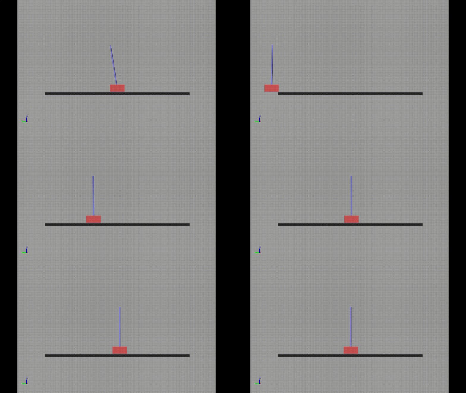
I need to define the matrix $Q$, $R$ and $N$. You can think of $Q$ as a matrix of weights that tell you how much to “penalize” certain combinations of the state. For instance the first term in the diagonal of the $Q$ matrix tells you how much to penalize the value of the state variable $x$. The same goes for other matrices. Having the $Q$ matrix as a scalar multiple of the identity matrix is a good default. $R$ is just a single scalar value. $N$ can be skipped in most cases. With these I got a control gain matrix that also successfully drove the states to my target. It looked quite similar to my hand tuned control gains actually. On close inspection you can see that the system does reach it’s target slightly faster.

Conclusion
Dynamics is an important part of a roboticist’s toolkit. Learning dynamics from a textbook can be a bit daunting. For me, implementing the ideas in code and generating nice animations helps me to get a better intuition of the mathematics. Now that I have the environment set up, I’m considering trying my hand at some swing-up control using energy shaping methods or reinforcement learning.